With the growing adoption of digital workflows, architects and engineers increasingly rely on CAD conversion services for old blueprints and scanned architectural drawings to transform hand-drawn sketches and legacy documents into accurate, editable CAD files. This allows professionals to handle large-scale projects, safeguard intellectual property, and enhance collaboration, ensuring design accuracy and streamlining project execution.
Architectural CAD conversion is the process of transforming paper-based blueprints and raster images into accurate, editable CAD files. In addition to improved precision and better storage, this process enables architects and engineers to make updates and modifications easily while preserving the original design details.
However, the conversion process comes with its own set of challenges. This blog discusses some of the most common challenges faced in architectural CAD conversion and the solutions.
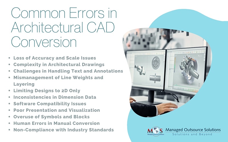
Common Errors in Architectural CAD Conversion
- Loss of Accuracy and Scale Issues
One of the main challenges in CAD conversion is ensuring accuracy. Poorly scanned or low-resolution blueprints can cause scaling and alignment issues, leading to errors in the final CAD drawing. This can compromise the design and create problems in construction or manufacturing.
In AutoCAD, viewports let you display different parts of your drawing at various scales. If you change a viewport’s scale without locking it, you risk accidental changes later, leading to inconsistencies. To avoid design errors and achieve professional results, it’s crucial to accurately map every detail into the CAD file.
- Complexity of Architectural Drawings
Architectural drawings often contain intricate details, layers, and annotations. One of the most common challenges in architectural CAD conversion is the vectorization of architectural drawings, where scanned blueprints or raster images must be accurately converted into editable vector formats without compromising on design precision. Converting these manually or using automated tools may result in missing elements, incorrect layer assignments, or distorted proportions, which can affect the overall quality of the converted CAD file. For instance, converted CAD files can sometimes be larger than expected, especially when dealing with high-resolution scans or complex designs. Large file sizes can slow down performance, making it difficult to share or work on them efficiently.
Drawing details on separate layers allow users to better distinguish objects. This approach eliminates the need to set properties for each object individually. Instead, you can assign properties to the layer, making it easier to manage and plot the drawing efficiently.
- Handling Text and Annotations
Text, dimensions, and annotations play a critical role in architectural drawings. One of the key steps in quality control during CAD conversion is resolving annotation and scaling problems to ensure that all notes, symbols, and dimensions are accurately represented. Converting these elements accurately while ensuring readability and correct placement is a challenge, as OCR (Optical Character Recognition) tools may not always interpret handwritten or stylized text correctly.
Manual verification is necessary to correct misinterpretations. Check annotation scaling and ensure that text sizes and annotations scale correctly when resizing drawings to maintain clarity. Ensure proper text placement by ensuring it remains aligned with relevant drawing elements to prevent miscommunication.
- Managing Line Weights and Layering
Layer management in CAD files is often overlooked during architectural conversions, but disorganized layers can make editing and collaboration extremely difficult. Proper layering and line weights are crucial for distinguishing different building elements, such as walls, doors, and electrical layouts. Inaccurate conversion may result in misclassified layers, making the final CAD file difficult to interpret and use.
Use a consistent naming convention for layers to categorize elements like walls, electrical components, and plumbing. Assign different line weights properly so that they represent various elements to maintain clarity.
- Limiting to 2D Designs
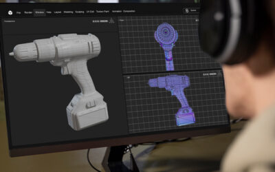
2D CAD and 3D CAD technology serve distinct purposes in architectural design and drafting. Understanding the differences between 2D and 3D CAD conversion for architecture is essential, as each process involves distinct workflows, data requirements, and output formats.
2D CAD is useful for creating flat drawings, plans, and elevations. It is suitable for technical documentation of floor plans, and basic layouts. However, 2D tools are not ideal for quick prototyping or concept design, which can make architects feel restricted in their experiments.
A better solution is 3D product modeling and rendering. 3D offers a three-dimensional representation of a structure, allowing users to visualize depth, spatial relationships, and realistic renderings. With these tools, designers and stakeholders can explore designs more thoroughly and identify errors early, helping to avoid unnecessary costs later on.
- Varying Dimension Data
Inconsistent dimension data can significantly impact CAD conversion by leading to errors in scaling, misalignment of components, and inaccurate representations of architectural elements. If dimensions vary between different sections of a drawing or are not clearly defined, the converted file may contain discrepancies that affect CAD data integrity.
Ensuring consistent and precise dimensioning is essential for achieving a high-quality CAD conversion. Smart dimensioning in AutoCAD offers the solution by clearly defining surfaces, shapes, and dimensions, ensuring your designs are communicated accurately.
- Compatibility Issues
Different CAD software programs have their own file formats and standards. CAD file compatibility issues can occur when converting files from one format to another (e.g., PDF to DWG, TIFF to DXF, or DWG to DXF conversion), especially when working with clients or teams using different software versions.
Overcoming interoperability challenges in architectural CAD software is key to ensuring seamless collaboration across different teams, tools, and file formats. Ensure that all team members and clients are using the latest versions of their CAD software to minimize compatibility issues. Proper communication between designers, project managers, and stakeholders can resolve issues and ensure the success of computer aided drafting.
- Poor Presentations
Discoloration, such as unnatural lighting, inconsistent shading, or incorrect material textures, can make a rendering look unrealistic and unappealing. Similarly, the lack of environmental data, such as background elements, shadows, reflections, or surrounding context can make the design feel isolated and lifeless.
Building Information Modeling (BIM) integration has become a critical component of modern architectural CAD conversion, enabling smarter collaboration and data-driven design. High-quality 3D renderings convey the architect’s vision more accurately by allowing clients to experience the design before construction. It offers a clear sense of scale, material finishes, and how the structure interacts with its surroundings. This level of detail improves communication between designers and clients, supporting informed decision making.
- Symbol Overload
Using too many symbols in CAD drawings can make them cluttered and hard to read. While symbols help represent different elements, overloading a drawing with them can hide important details and make it confusing. This can lead to mistakes, miscommunication, and wasted time trying to understand the design. Keeping symbols to a necessary minimum helps keep drawings clear and easy to use.
- Human Errors in Manual Conversion
If the conversion process involves manual tracing or redrawing, human errors such as misinterpretation of details, incorrect dimensions, or omission of small elements can occur, affecting the overall accuracy of the CAD file. Stringent quality checks can prevent manual errors.
- Compliance with Industry Standards
Different regions and industries follow specific CAD drafting standards. Ensuring that the converted CAD files adhere to these standards (such as AIA, ISO, or local building codes) can be challenging, especially when converting legacy drawings.
Achieve Precision with Expert CAD Conversion Support
By addressing these common issues, businesses can streamline their CAD conversion process and improve the efficiency of architectural design workflows. High-quality architectural CAD conversion is often time-consuming, particularly for large or highly detailed projects. It requires careful attention to detail to ensure that accuracy, compatibility, and industry standards are maintained. Partnering a company that specializes in architectural cad conversion services can overcome these challenges. Experts adhere to best practices for architectural blueprint conversion to CAD by leveraging advanced conversion tools and implement extensive quality control checks to ensure the accuracy of the converted files, allowing you to stay competitive in the dynamic field.
Discover how our conversion solutions can save you time and costs-
Get in touch now